Showing posts with label ps5. Show all posts

Sunday, June 28, 2020

Sony PlayStation 5 Price, Release Date, Design, Games, Controller

Sony PlayStation 5  Price, Release Date, Design, Games, Controller
PS5 release date, design, specs and news for Sony's PlayStation 5 ...

After months of hints and small reveals, Sony’s PS5 is finally out in the public eye. The company revealed its next-gen console in a games-focused livestream the other week, highlighting some of the exclusive and mutliplatform games coming to the new machine. We also got to see the box for the first time, something Microsoft did with its Xbox Series X back in January. Between that and earlier reveals, we have a fair amount of information about the thing right now, so let’s get into a roundup of everything we know so far, as well as predictions about what we don’t. So here’s the PS5: it’s design, specs, and games, as well as predictions about the price and release date.

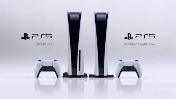
Design: It’s a weird one! Consoles have either been black boxes or made by Nintendo for as long as I can remember, but the PS4 is going for a sort of mod spaceship look, with big white plastic fins on the side. There are two versions: one with a disc drive bumping out, and one without. Both are gigantic, and likely the biggest console you’ve ever owned.

Take a look here:
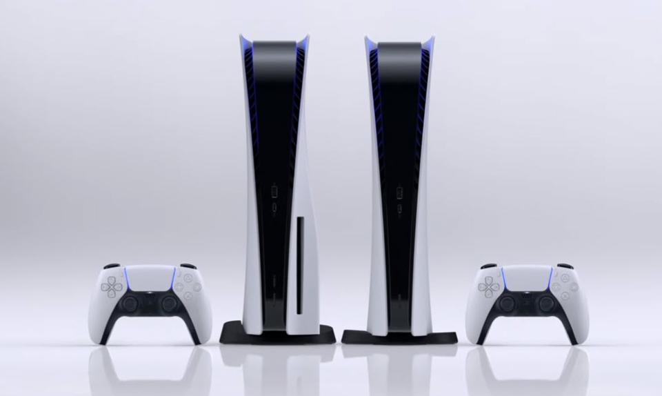
Release Date: A question mark, though not quite such a big question mark as price. Consoles typically come out in November as prep for the holiday season: the PS4 came out on November 15, and the PS3 came out on November 17 (in North America). Before that, things were not quite as standardized, but nobody really expects things to change all that much. Look for something in late November, maybe 19 or 20.

Specs: Sony revealed the specs for the console before it showed the machine itself, so we know what’s inside the box:

  • CPU: AMD Zen 2-based CPU with 8 cores at 3.5GHz (variable frequency)
  • GPU: 10.28 TFLOPs, 36 CUs at 2.23GHz (variable frequency)
  • GPU architecture: Custom RDNA 2
  • Memory interface: 16GB GDDR6 / 256-bit
  • Memory bandwidth: 448GB/s
  • Internal storage: Custom 825GB SSD
  • IO throughput: 5.5GB/s (raw), typical 8-9GB/s (compressed)
  • Expandable storage: NVMe SSD slot
  • External storage: USB HDD support (PS4 games only)
  • Optical drive: 4K UHD Blu-ray drive   

Games: This is a little confusing, because the PS5 will be backwards compatible, and there are a bunch of cross-gen games that will also receive upgrades for newer hardware. So not only will anything you have on the PS4 will run on the PS5, major AAA releases like Assassin’s Creed: Valhalla, Cyberpunk 2077 and whatever the new Call of Duty is will be made to take advantage of more horsepower.

Beyond that, Sony announced a bunch of exclusive and non-exclusive titles in its recent showcase. Here’s a list of those. We’re not getting a major first-party AAA release title, but we are getting Spider-Man: Miles Morales a smaller standalone title releasing for the holiday season. The first full-scale exclusive will be Horizon: Forbidden West, out in 2021, though we don’t know when.
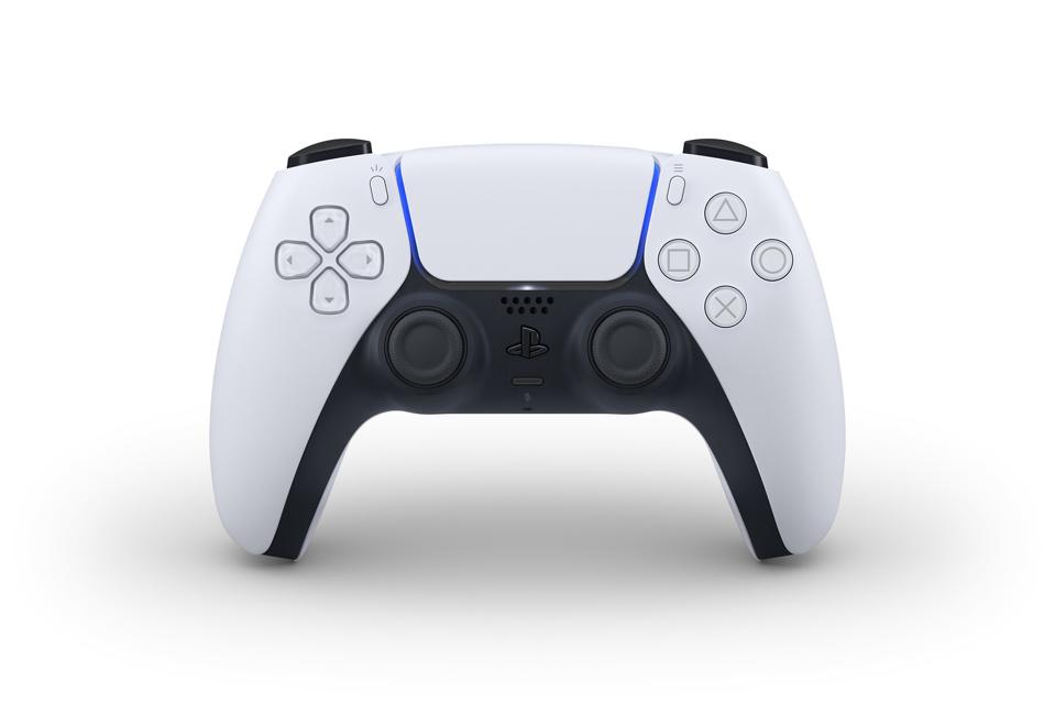
Dualsense

Controller: We actually saw the Dualsense controller long before the console itself, and the white/black two-tone design certainly makes more sense it context. That’s what we can see, however. What’s more exciting is what we can’t see yet: the Dualsense is coming with state of the art haptics and feedback mechanisms. I don’t want to get too excited, because it’s impossible to evaluate this stuff without a controller in its hand, and rumble effects have been overhyped before. I have, however, read impressions from developers who are impressed with the experience overall, so I’m cautiously optimistic.

Price: This one is arguably the biggest question of the entire console. We do not yet have a confirmed price, but we do have an idea of where it might fall. What we know is that there will be not one but two prices: one for the all-digital edition, and one for the disc drive edition. If the all digital edition is cheaper, most suspect a price differential of $50-$100. $100 would be a lot more than the cost of the disc drive, but there is always the possibility that Sony would be hoping to make it up through committing players to buying on PSN.

Few expect the price to go as high as $599, the eye-watering price that crippled the PS3 at launch, but it’s not totally impossible. If that’s the upper bound, the lower bound is probably $399, which is where the PS4 launched.

Most expect one of these two machines to be $499, so the breakdown could go $549/$499, or $499/$449. If we’re looking at a $50 price differential, my guess is it would be one of those two.

If we’re looking at a 365AED  price differential, it’s not impossible that we would start edging up at one of those two bounds: either $599/$499 or $499/$399.

Tuesday, June 23, 2020

Sony PlayStation 3 fat Yellow Light of Death Repair

Introduction

Use this guide to repair PlayStation 3s with the "Yellow Light of Death" error.

Note: Your PlayStation may look slightly different inside. Be cautious when performing this process on your machine.


Video Overview

  •  
  •  
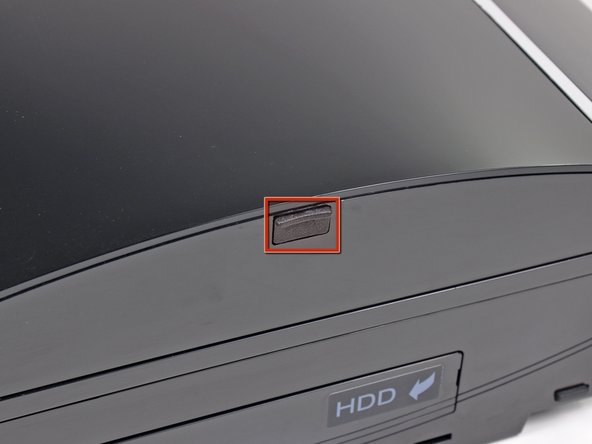
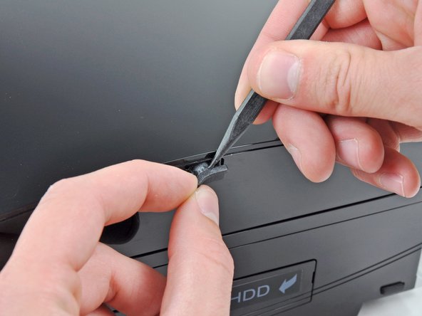
  1. Use the tip of a spudger to remove the black rubber screw cover from the side of the PS3.
    • Use the tip of a spudger to remove the black rubber screw cover from the side of the PS3.

    • The screw cover may be underneath a warranty sticker. This sticker will change appearance, and show "VOID" after it has been removed.

  2. Remove the single 8.5 mm T10 Security Torx screw from the smart plate.
    • Remove the single 8.5 mm T10 Security Torx screw from the smart plate.

  3. Pull the smart plate toward the hard drive bay, then lift it off the body of the PS3.
    • Pull the smart plate toward the hard drive bay, then lift it off the body of the PS3.

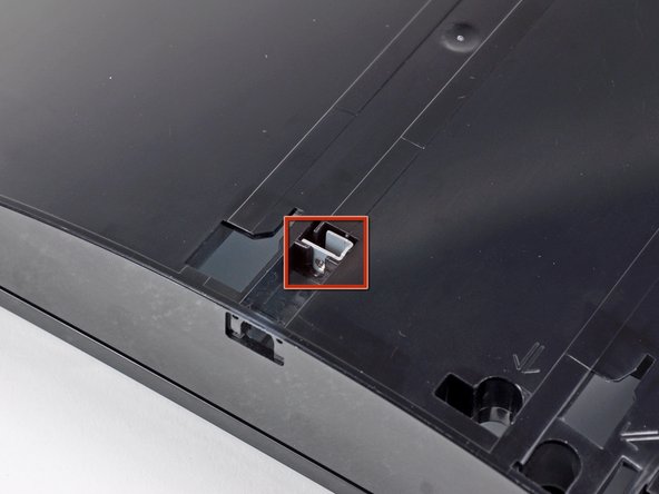
  4. Be sure to keep track of the small metal bracket loosely held in the top cover, if equipped.
    • Be sure to keep track of the small metal bracket loosely held in the top cover, if equipped.

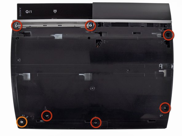
  5. Remove the following seven screws:
    • Remove the following seven screws:

    • Six 52 mm Phillips screws

    • One 30 mm Phillips screw

  6. Lift the top cover from its rear edge and rotate it toward the front of the PS3.
    • Lift the top cover from its rear edge and rotate it toward the front of the PS3.

    • Remove the top cover.

    • There is a plastic hook located in a hole on the top back right hand side corner. Carefully push the plastic hook a bit front the rear of the machine with a spudger to release the rear right of the casing.

  7. Disconnect the Blu-ray power cable from the motherboard.
    • Disconnect the Blu-ray power cable from the motherboard.

    • Pull the connector straight up and out of its socket.

  8. Lift the Blu-ray drive from the edge nearest the power supply and rotate it away from the chassis enough to access its ribbon cable.
    • Lift the Blu-ray drive from the edge nearest the power supply and rotate it away from the chassis enough to access its ribbon cable.

  9. Pull the ribbon cable out of its socket.
    • Use your fingernail to flip up the retaining flap on the Blu-ray ribbon cable socket.

    • Be sure you are prying up on the retaining flap, not the socket itself.

    • Pull the ribbon cable out of its socket.

    • Remove the Blu-ray drive from the PS3.

    • If replacing the Blu-ray drive, transfer the power cable to your new drive.

  10. Pull the control board ribbon cable straight up and out of its socket on the motherboard.
    • Pull the control board ribbon cable straight up and out of its socket on the motherboard.

  11. Remove the two 12 mm Phillips screws securing the control board to the lower case.
    • Remove the two 12 mm Phillips screws securing the control board to the lower case.

    • Remove the control board and its attached cable from the PS3.

  12. Remove the following eight screws securing the motherboard assembly to the lower case:
    • Remove the following eight screws securing the motherboard assembly to the lower case:

    • Seven 12 mm Phillips screws (ph2)

    • One 30 mm Phillips screw

  13. Remove the control board bracket.
    • Remove the control board bracket.

  14. Use the flat end of a spudger to pry the hard drive bay cover away from the lower case.
    • Use the flat end of a spudger to pry the hard drive bay cover away from the lower case.

    • Remove the hard drive bay cover.

  15. Lift the motherboard assembly out of the lower case.
    • Lift the motherboard assembly out of the lower case.

  16. Remove the 7.7 mm Phillips screw securing the ground strap to the chassis.
    • Remove the 7.7 mm Phillips screw securing the ground strap to the chassis.

  17. Pull the AC-In cables slightly away from the rear cover for clearance to access the AC-In connector.
    • Pull the AC-In cables slightly away from the rear cover for clearance to access the AC-In connector.

    • While depressing its locking mechanism, pull the AC-In connector out of its socket on the power supply.

  18. Free Yourself From Outlets

    Improve your laptop battery, improve your life

    Shop Mac Battery Fix Kits
  19. Pull the AC inlet out from the bottom of the rear cover, minding any of its cables that may get caught.
    • Pull the AC inlet out from the bottom of the rear cover, minding any of its cables that may get caught.

  20. While lightly pulling the rear cover away from the logic board assembly, use the flat end of a spudger to release the clips along the top and bottom edges of the rear cover.
    • While lightly pulling the rear cover away from the logic board assembly, use the flat end of a spudger to release the clips along the top and bottom edges of the rear cover.

  21. Remove the rear cover from the logic board assembly.
    • Remove the rear cover from the logic board assembly.

  22. De-route the fan cables from the plastic finger molded into the heat sink.
    • De-route the fan cables from the plastic finger molded into the heat sink.

    • Disconnect the fan from the motherboard.

    • Pull the connector straight up and out of its socket.

  23. Remove the two 9 mm Phillips screws securing the memory card reader to the chassis.
    • Remove the two 9 mm Phillips screws securing the memory card reader to the chassis.

  24. Lift the memory card reader out of the PS3 enough to access its ribbon cable.
    • Lift the memory card reader out of the PS3 enough to access its ribbon cable.

    • Flip up the retaining flap on the memory card reader ribbon cable socket.

    • Be sure you are prying up on the retaining flap, not the socket itself.

    • Pull the ribbon cable out of its socket and remove the memory card reader.

  25. Disconnect the DC-In cables from the front of the heat sink.
    • Disconnect the DC-In cables from the front of the heat sink.

    • Pull the connector toward the front of the PS3.

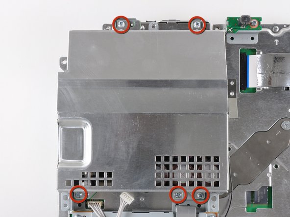
  26. Remove the five 9 mm Phillips screws securing the power supply to the chassis.
    • Remove the five 9 mm Phillips screws securing the power supply to the chassis.

  27. Lift the power supply by its front edge to clear the two posts attached to the motherboard.
    • Lift the power supply by its front edge to clear the two posts attached to the motherboard.

    • Remove the power supply.

  28. Remove the four 16.5 mm shouldered Phillips screws securing the heat sink to the motherboard.
    • Remove the four 16.5 mm shouldered Phillips screws securing the heat sink to the motherboard.

    • Remove the two brackets held under the screws you just removed.

  29. Lift the motherboard assembly off the heat sink.
    • Lift the motherboard assembly off the heat sink.

    • The heat sink may still be held in place by the thermal paste. If this is the case, gently pry the heat sink away from the motherboard housing. Make sure to not bend the copper piping on the heat sink.

    • Be sure to apply a new layer of thermal paste when reattaching the heat sink.

    • Never applied thermal paste before? Our thermal paste guide makes it easy.

    • If you're following the YLOD repair guide, stay tuned for where to apply the replacement thermal paste.

  30. Flip up the retaining flap on the Blu-ray ribbon cable socket.
    • Flip up the retaining flap on the Blu-ray ribbon cable socket.

    • Be sure you are prying up on the retaining flap, not the socket itself.

    • Remove the Blu-ray ribbon cable.

  31. Flip up the flap on the memory card reader ribbon cable socket and remove the ribbon cable.
    • Flip up the flap on the memory card reader ribbon cable socket and remove the ribbon cable.

  32. Flip up the retaining flap on the Wi-Fi/Bluetooth ribbon cable socket.
    • Flip up the retaining flap on the Wi-Fi/Bluetooth ribbon cable socket.

    • Pull the Wi-Fi/Bluetooth ribbon cable out of its socket.

  33. Disconnect the DC-In cable from the motherboard and set it aside.
    • Disconnect the DC-In cable from the motherboard and set it aside.

    • Pull the connector straight up and out of its socket on the motherboard.

  34. Disconnect the PRAM battery from the motherboard.
    • Disconnect the PRAM battery from the motherboard.

    • The PRAM socket is delicate and has the potential to break off the motherboard. If possible, hold down the socket as you disconnect the PRAM battery cable.

  35. Rotate the PRAM battery slightly counter-clockwise and remove it from the motherboard assembly.
    • Rotate the PRAM battery slightly counter-clockwise and remove it from the motherboard assembly.

  36. Remove the blue 8 mm Phillips screw securing the hard drive cage to the chassis.
    • Remove the blue 8 mm Phillips screw securing the hard drive cage to the chassis.

  37. Push the hard drive cage toward the front of the motherboard assembly.
    • Push the hard drive cage toward the front of the motherboard assembly.

    • Remove the hard drive from the motherboard assembly.

  38. Remove the two 3.7 mm #0 Phillips screws securing the chassis to the hard drive socket.
    • Remove the two 3.7 mm #0 Phillips screws securing the chassis to the hard drive socket.

  39. Remove the two 8.3 mm #0 Phillips screws securing the two halves of the motherboard together.
    • Remove the two 8.3 mm #0 Phillips screws securing the two halves of the motherboard together.

  40. Carefully feed the Wi-Fi/Bluetooth ribbon cable through the hole in the top motherboard cover.
    • Carefully feed the Wi-Fi/Bluetooth ribbon cable through the hole in the top motherboard cover.

    • Remove the top motherboard cover.

  41. Remove the motherboard from the bottom motherboard cover.
    • Remove the motherboard from the bottom motherboard cover.

  42. Flip up the retaining flap on the Wi-Fi/Bluetooth ribbon cable socket.
    • Flip up the retaining flap on the Wi-Fi/Bluetooth ribbon cable socket.

    • Remove the Wi-Fi/Bluetooth ribbon cable from the motherboard.

    • Motherboard remains.

    • Using the flat end of the spudger, remove the old thermal paste off the CPU and GPU on the motherboard.

    • Using a cleaner such as Arctic Silver's ArctiClean or high alcohol content rubbing alcohol, clean the CPU and GPU.

    • Clean the thermal paste off of the heat sink in the same way.

  43. Using your fingers or the flat end of a spudger, remove the old thermal pads on the logic board as indicated:
    • Using your fingers or the flat end of a spudger, remove the old thermal pads on the logic board as indicated:

    • Large square thermal pads

    • Small square thermal pads

    • Small rectangular thermal pads (located on the underside of the board, as highlighted in the second picture)

    • Some of the smaller thermal pads may be attached to the metal casing that surrounds the motherboard rather than the motherboard itself.

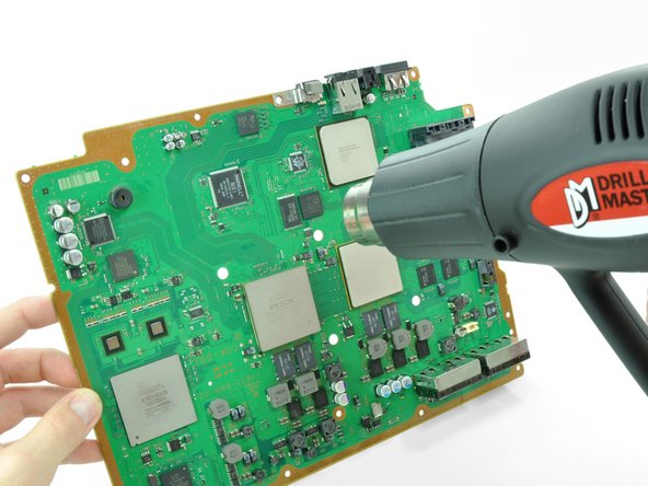
  44. Set the heat gun to "Low", and let it run for a few seconds to reach operating temperature.
    • Set the heat gun to "Low", and let it run for a few seconds to reach operating temperature.

    • Holding the motherboard upright, warm up the entire board with the heat gun. The board should be warm, but not too hot.

    • This will prevent damage to the board caused by localized thermal expansion.

  45. Set the motherboard on a support so that the CPU and GPU are completely supported and level.
    • Set the motherboard on a support so that the CPU and GPU are completely supported and level.

    • The support should be something that can resist temperatures upwards of 300 degrees Celsius. Suggestions: scrap lumber, old books, cardboard box.

    • In the next few steps, you will be reflowing the solder under the chips marked in red.

    • Once you begin reflowing the chips, do not touch or move the motherboard until it is completely cool. Doing so can render the motherboard irreparably damaged.

  46. Using a circular motion, evenly heat (using low heat) each of the four areas for roughly 25 seconds each.
    • Using a circular motion, evenly heat (using low heat) each of the four areas for roughly 25 seconds each.

    • Begin heating the GPU, marked "RSX", and heat the chips in a zig-zag order.

  47. Continue heating the chips using the same circular motion as described above, for about 25 seconds each.
    • Continue heating the chips using the same circular motion as described above, for about 25 seconds each.

  48. Ensure that the motherboard has completely cooled before continuing this guide.
    • Ensure that the motherboard has completely cooled before continuing this guide.

    • If you have not applied thermal paste before you can check our thermal paste guide whilst it is cooling.

    • Apply a thin bead of thermal paste on the CPU.

    • Using the thermal paste spreader card, spread the paste out thinly and evenly on the chip.

    • In the same way, apply a thin layer of thermal paste on the GPU.

    • Clean up any excess thermal paste off the motherboard.

  49. Apply the fresh thermal pads to the motherboard in the locations indicated:
    • Apply the fresh thermal pads to the motherboard in the locations indicated:

    • Large square pads

    • Small square pads

    • Small Rectangular Pads

    • If you'd like to cut your own thermal pads, you'll need material about 2-2.5mm in thickness. Thanks to user howardsarah34 for the exact measurements for the thermal pads.

    • Two 3cm x 3cm Squares

    • Ten 1cm x 1cm Squares

    • Five 1.5cm x 0.5cm rectangles

  50. Peel the remaining white plastic cover off the other side of thermal pads.
    • Peel the remaining white plastic cover off the other side of thermal pads.